I haven't been doing a very good job of keeping this thread up to date with progress. I have been updating my
blog regularly, but unfortunately not this thread on sprinter-source - which has provided me with so much value. I'll try to get better with that.
Anyway - on to more build information.
The Heater Install....
Honestly I think installing the heater was the hardest thing we have done in the fan so far. It’s not particularly difficult, but there are a lot of parts and pieces, do’s and don’ts, and in’s and out’s (inside and outside work, that is).
Summary (TL

R):
Purchased the Eberspacher/Espar D2 heater kit from
www.heatso.com which is a company based in the UK. It shipped super fast and even with the import tax was still way cheaper than any deals we could find here. The install package came complete with everything we needed to install except for good instructions – which we put together from various posts and manuals found online. Installed the heater under the passenger seat. It works!
Tools:
- Drill
- Large hole saw bits (2″ + i think)
- hack saw or saws-all
- soldering iron
- grinder
- wrenches, ratchets, screw drivers, etc.
- patience
- Materials:
Espar/Eberspacher D2heater kit
A short (12”) piece of 5/16” black flexible fuel line
two hose clamps
metal male-male 1/4″ barbed connector
solder, heatshrink tubing, electrical tape, etc.
aluminum / heat reflective tape (same stuff we used on the reflectix) for use as a heat shield
rust inhibiting paint (for touch up)
butyl tape – for sealing around the mounting flange
zip ties
Reference:
The references above are really good so given that, I am not going to go through my usual detailed process here. I will highlight some of the specific things that we did.
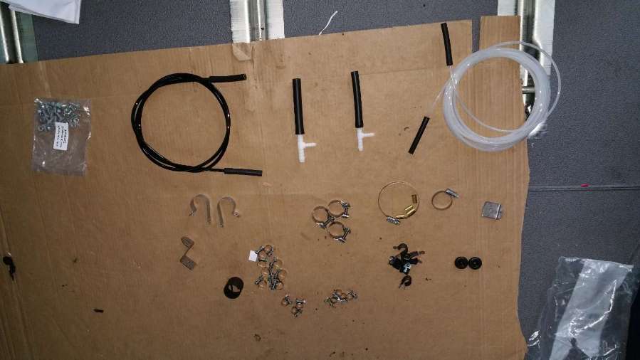
The install kit that came with our heater really had everything we needed for the install, save fore the items listed above. All kinds of good fittings for various install options. There were a few barbed tee fittings which I guess are used for if you are cutting into an existing accessory fuel line (like if you have the factory oem espar installed under the hood). Since we didn’t need to do that, we didn’t use several of the pieces, but it was nice to know we had them.
When I first opened the box I freaked out – OMG there are a lot of things in here. But when you break it down it really isn’t that complicated (really). On the heater you have:
- Combustion air inlet (intake, 25mm)
- Combustion air outlet (exhaust, 24mm – smaller!)
- fuel intake
- power wire loom (with a few wires in it)
- control wire loom (with a whole bunch more wires in it – but you don’t need most of them!)
We decided we wanted to put our heater under the passenger seat. This was mostly because we have no idea how we are going to ‘finish’ the rest of our van, in terms of furniture, cabinetry, tables, and the like – so putting it under the passenger seat seamed like a good “no consequence” place to start cutting more holes in the van. We were pretty sure with it under there that we wouldn’t be tripping over it in the future.
So the front passenger seat came out. Since we have heated seats and those side airbags there were a few electrical cables to undo. These were easy enough to detach at their connectors but be warned: I am told that if you start the vehicle with these cables detached you will get a persistent fault (even after you reattach them) regarding the ABS system. This is easy to reset/clear at the dealer I guess, but I didn’t want to risk it. I didn’t test out if this warning is true. I just made sure to connect the seat back in before starting the vehicle (or even putting the key in the ignition). Maybe others will be bolder and can tell me I’m wrong – that’s fine.
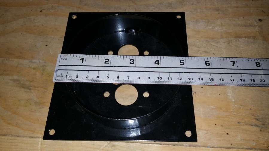
We ordered the heater with this nice installation bracket. When it came, I had no idea how it was supposed to work. It also came with this nice rubber gasket. Since I forgot to take a nice picture of the gasket and how all of this stuff was (maybe) supposed to go together, I built a 3D model instead.
So how does that work? See the model below…
Left side: the gasket appears to be perfect for the bottom of the heater, but if you put it on the bottom of the heater, how does it fit into the cylinder portion of the mounting bracket?
Right side: Am I really supposed to cut a 5″ hole in the bottom of the van for the “cylinder” of the mounting bracket to fit in? Doesn’t leave a lot of sealing surface between the van floor and the flange.fan mount question
After staring at the heater, the gasket and the mounting flange for about three hours I decided there was no hope and I couldn’t figure out how to make the three of them work together. I probably could have emailed and/or called heatso and they would have helped me (sprintervandiaries says they were very helpful) but I didn’t do that – I guess I tend to stress the Y in DIY. Anyway – after careful deliberation, I decided to take matters into my own hands and ‘customize’ the mounting bracket. I cut the cylinder portion of the mounting bracket of with the grinder. It was just 4 welds and went pretty fast.
This is the setup I went with ultimately. Without the cylinder attached to the flange I had a nice flat mounting surface to place the gasket on and a nice flat surface to mount against the van floor. I used butyl tape to seal between the mounting flange and the floor of the van (yes! the same tape we used for mounting the fan on the roof!!). The layup order is (from outside to inside):
- van floor
- butyl tape
- mounting flange
- rubber gasket
- heater
- heater bolted up
The mounting flange also served as a great template for drilling the holes. And because the flange was sealed against the floor of the van, I could oversize the holes in the floor of the van (for some wiggle room) and not worry at all about having a leak. Bolts in the bottom of the fan and bolts in the mounting flange all went through the van floor with washers and nuts on the other side (outside of the van) to hold everything nice and snug together. Ultimately I have to say this worked out very nicely.
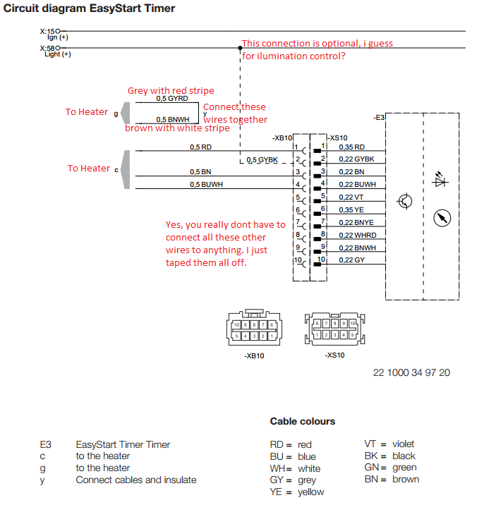
The second hard part was wiring the controller. We ordered our heater with the “easy start timer”. The kit came with an install CD and while the wiring instructions were espar - easy start wiring annotationplentiful, they weren’t exactly straightforward – well at least not to me. Actually, now looking back they are very straightforward – I was just so thrown off that there were a bazillion wires coming off of the easy start timer module and a whole bunch coming from the heater, but you only connect to 3 of the wires from the espar wire loom and connect to wires from the espar together. Really, that is it. I have annotated the wiring diagram for your (and my) reference.
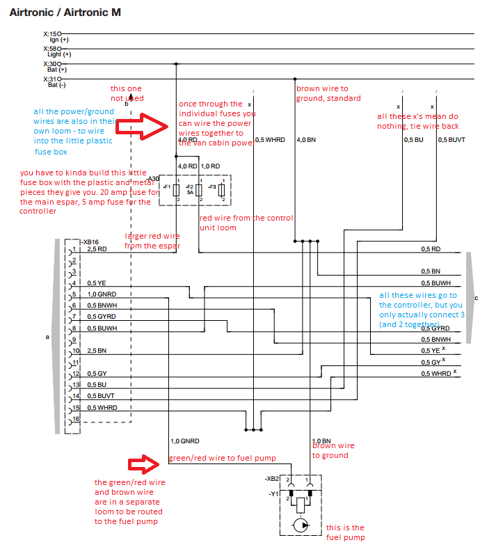
Wiring of the main heater itself is pretty straightforward. You have three main wire looms: (1) the control unit wiring bundle. (2) the power wiring bundle (with the red wires). (3) the fuel pump power/ground bundle. Its pretty straightforward which one is which. And I have annotated another diagram, for reference.
BIG NOTE: we did not get the high altitude adapter and thus have no reference to wiring for that. sorry.
For the rest of the details, I am going to go ahead and say check out the references. especially this one from sprintervandiaries. because its very detailed.
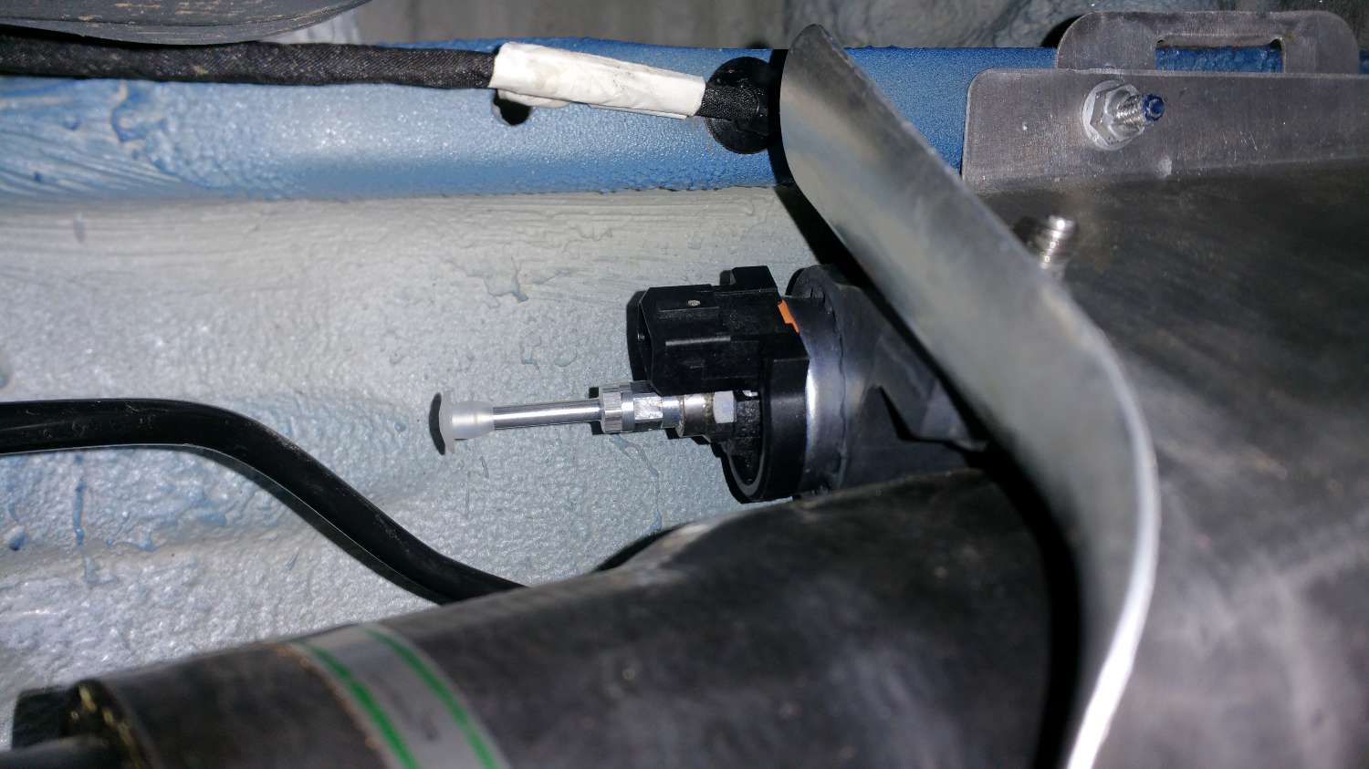
I mounted the fuel pump inside the aluminum protector that covers the main sprinter diesel fill line. I liked the idea that it would be protected from debris getting kicked up from the road. However, the routing of the intake hose from the OEM auxilliary fuel pick-up was a little tricky (it does a u-turn into the fuel pump) and may not be the best routing. it seems to work for now. To do it, I just pulled of the aluminum protector, drilled a hole in it at the “right” spot and then bolted the pump to it.
On the close up, you can see its a tight squeeze between the sprinter fuel filling pipe, the fuel pump, and the OEM auxiliary fuel pick-up line going the other direction. You can also see the hose clamp over the 5/16″ rubber hose. As mentioned in the sprintervandiaries post – it was really quite difficult to get the 5/16″ hose over the factory fitting. but using a heat gun helped.
Because or heater was installed on the opposite side of the van as the fuel tap, we routed the fuel line across the vehicle, using lots and lots of zip ties as well as ‘heat shielding’ the fuel line with the reflectix tape where it crossed the exhaust and other ‘hot’ parts.
That pretty much covers this installation.

 91.4 KB Views: 734
 136.6 KB Views: 707