External Alternator Regulator For Battery Charging

rollerbearing

Well-known member
In thinking about the "W" or Stator input to the the voltage regulator and the reason for the intelligent regulator needing to know the RPM of the alternator: it is possible that the regulator may limit the alternator output based on RPM in order to ensure adequate fan cooling. The designers may have just come up with an output profile based on fan capacity.
 
Last edited:

rollerbearing

Well-known member
In thinking about the "W" or Stator input to the the voltage regulator and the reason for the intelligent regulator needing to know the RPM of the alternator: it is possible that the regulator may limit the alternator output based on RPM in order to ensure adequate fan cooling. The designers may have just come up with an output profile based on fan capacity.

PS:

Reading through this data sheet

http://www.bosch-motorsport.de/cont...rnator_B3_LIN_Datasheet_51_en_13619552267.pdf

I guess I'm more inclined now to think that the primary use for the stator "W" signal is for the 3000RPM cut-in on this alternator.

Nice clear Ioutput vs RPM plot in there too.
 

calbiker

Well-known member
If I got this straight, you inserted a diode in the positive side, as described by SmartGauge? That would make me feel better.

http://www.smartgauge.co.uk/alt_mod.html

That's the right way to do it. I'm pretty sure you don't need the second diode which is called a flyback diode. It looks like there's a flyback diode on your circuit board between the two brush connections. You can detect this diode on your removed regulator by using your ohm meter set on diode scale. From brush to brush, you should see a diode drop one way and not the other. Even though the regulator regulates more or less constant current, the voltage switches on and off pwm style. The inductance of the rotor produces a big voltage spike when it gets switched off which the flyback diode suppresses.

*********************************************************

Edit, on second thought if you have the suppression diode in, then keep it in. It does no
harm.
 
Last edited:

Midwestdrifter

Engineer In Residence
In thinking about the "W" or Stator input to the the voltage regulator and the reason for the intelligent regulator needing to know the RPM of the alternator: it is possible that the regulator may limit the alternator output based on RPM in order to ensure adequate fan cooling. The designers may have just come up with an output profile based on fan capacity.
I am inclined to agree. I think the voltage regulation may be directly controlled via analog comparator, but fault detection, and startup control is digital. I would not be surprised if there a thermistor on the board that will throttle output based on heatsink temps.

PS:

Reading through this data sheet

http://www.bosch-motorsport.de/cont...rnator_B3_LIN_Datasheet_51_en_13619552267.pdf

I guess I'm more inclined now to think that the primary use for the stator "W" signal is for the 3000RPM cut-in on this alternator.

Nice clear Ioutput vs RPM plot in there too.
Yeah, definitely resembles the blower flow vs rpm plots I have seen.

If I got this straight, you inserted a diode in the positive side, as described by SmartGauge? That would make me feel better.

http://www.smartgauge.co.uk/alt_mod.html

That's the right way to do it. I'm pretty sure you don't need the second diode which is called a flyback diode. It looks like there's a flyback diode on your circuit board between the two brush connections. You can detect this diode on your removed regulator by using your ohm meter set on diode scale. From brush to brush, you should see a diode drop one way and not the other. Even though the regulator regulates more or less constant current, the voltage switches on and off pwm style. The inductance of the rotor produces a big voltage spike when it gets switched off which the flyback diode suppresses.

*********************************************************

Edit, on second thought if you have the suppression diode in, then keep it in. It does no
harm.
Yes, the diode is on the B+ feed (for both field and regulator). I don't see any issues with the ground side mod, but I am no expert by any means.

I also don't think the flyback diode is necessary, but I had spares, and it can't hurt anything in that configuration. I have seen a few ICs destroyed by inductive voltage spikes, no reason to take that risk.

Is the voltage at the battery bank still increased?

It occurred to me that we have teased this regulator apart enough now that we understand it pretty well. With that knowledge you could make it do a primative form of remote sensing. That is, pick up V+ for the regulator at the battery and thereby compensate for the cable drops. Not sure that will make much difference if your alternator is limited by the RPM you wish to charge at. But it's still something to ponder. How practical it really is - I'm not entirely sure as the entire field current needs to be delivered down the "sense" wire which introduces it's own voltage drops.

With the system as it stands now perhaps with the slight voltage boost your alternator could still be run for a shorter time at an increased RPM than it would have needed to be otherwise. So still an overall improvement.

You could artificially boost up V+ past B+ in order to drive the field coil harder - but i think that might be treading on dangerous ground with the original regulator. There does appear to be brush ony units which would allow you to convert the alternator easily to an external regulator.
Generally I only run up against the alts output limits if the bank is below 75% SOC. Even then its only for about 15 minutes. Below 60% I can max the alt out for a bit longer, maybe more so at the higher voltage.

The biggest limiting reason for the upped voltage is faster absorb. Getting the last 10% into the battery takes less than half the time at 14.4V as it does at 13.9V. The faster charging below 90% SOC is just a bonus.

I thought about remote sensing. The issue is that my Aux bank charges through a VSR relay (blue sea ML-ACR). If it became disconnected during operation the alt would stop charging. If the sense wires resistance got to high, a dangerously high voltage spike could occur. Bad mojo. Failsafes could be rigged up, but at that point I might as well just solder in an external regulator!

If only the external regulators weren't so expensive... The other issue is that an external regulator really needs RPM/output limits and or temperature feedback. After your research, I know believe that these small case alternators can only produce 200A (or 150A etc) from such a small package because they adaptively regulate output to stay within the cooling limits.
 
Last edited:

HarryN

Well-known member
The higher power alternators I looked at were in somewhat larger cases and most had 6 or 12 phase windings.

The external regulators often have higher performance diodes built in with very low Vf. Schottky diodes that can handle 400 - 500 amps, higher frequencies (for 12 phases at x000s of rpm) and have a low Vf start to get expensive. I have paid $75 / each for premium ones. Obviously those are not used in standard automotive alternators.

Putting the diodes in the external regulator helps gain space in the alternator, but also moves a lot of heat away from the alternator itself.

It looks like you have a really good solution that will help a lot with your power needs. Great job with a lot of good creative inputs from people that understand alternators far better than I do.
 

calbiker

Well-known member
Inductance kickback can be nasty. Need to treat it with respect. I recall fixing a problem on a military machine gun that mounts on vehicles. The trigger pulls in a relay, the relay contacts energizes the guns solenoid and the gun shoots. The relay contacts are well within the ratings of the solenoid current. If the gun is set to single shot fire and the gunner fires at a rapid rate, the relay contacts get so hot that they fuse together and the gun now fires uncontrollable at full speed. The solenoid's inductance generates a high voltage spike across the contacts as they open. The spark heats the contacts enough to fuse them. That's why you got a capacitor across the distributor point in cars.

I also don't think the flyback diode is necessary, but I had spares, and it can't hurt anything in that configuration. I have seen a few ICs destroyed by inductive voltage spikes, no reason to take that risk.
 

HarryN

Well-known member
Inductance kickback can be nasty. Need to treat it with respect. I recall fixing a problem on a military machine gun that mounts on vehicles. The trigger pulls in a relay, the relay contacts energizes the guns solenoid and the gun shoots. The relay contacts are well within the ratings of the solenoid current. If the gun is set to single shot fire and the gunner fires at a rapid rate, the relay contacts get so hot that they fuse together and the gun now fires uncontrollable at full speed. The solenoid's inductance generates a high voltage spike across the contacts as they open. The spark heats the contacts enough to fuse them. That's why you got a capacitor across the distributor point in cars.
That had to be an interesting experience.
 

Midwestdrifter

Engineer In Residence
A new behavior has shown itself. Likely a bug in the cheap regulator I am using.

With the engine idling, if I suddenly remove a load from the aux battery, something around 80-90A, the regulator will shut down. I assuming some type of spike in the field voltage, or internal protection. The Alt immediately cuts out. Dash light comes on etc.

For those curious, with no accessories running the engine uses about 15-20A.

A restart fixes the problem. It is repeatable. It wasn't doing it yesterday, so it may be related to alternator temperature, or maybe having the solar charging outputting at the same time? I will fiddle with it a bit.


If I drop the load in two stages (80 then 50, then off) the cut-out does not occur.

Also worth mentioning, is that this regulator was advertised for 150A alternators. The Bosch part it replaces if for 90-200A units, so I took a bit of a gamble.


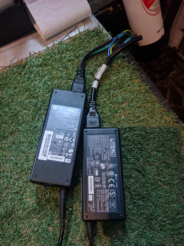
Also here is a shot of my poor mans shore charger. Two 60W (actually a 90 and a 60) laptop power bricks wired in series for 38V. I have this paralleled with my solar array. Multi-stage charging for less than 100$. Yay!

IMG_20180527_160155 by J Luth, on Flickr
 

rollerbearing

Well-known member
Interesting. Did you get the diode bypass relay wired up? Does it do this same thing with the diode bypassed (shorted over)?

And - it sounds like the error "latches" - that is you have to shut the whole system down to clear it?

Only thing I can think of - and it's a real stretch that I can't quite see - is maybe that second diode has gone into breakdown due to the sudden current unloading and the resulting back emf from something????????

Otherwise it could be just about any weird old thing in the PIC programming (intentional or unintentional).
 
Last edited:

Midwestdrifter

Engineer In Residence
I will bypass it with a jumper tomorrow to test. I suspect it is probably just the regulator being a cheapo, and not quite up to the task.

Yeah, the error sticks until restart. I am sure it is a failsafe in the program. For example, it may think that the output got disconnected due to the voltage rise rate, so it just cuts the field to stop a mega voltage spike.
 

calbiker

Well-known member
Is the alternator self starting or does it need an excitation to re-start?

Don't recall the name, is it the DF signal coming from Instrument Cluster that provides the initial rotor current? It's been reported (with Bosch regulator) if the DF signal is lost the alt will self start when engine is reved above 2500 rpm.

Edit: When the alt gets in the non-functional state, I would measure the DF (?) voltage when engine is running. The excitation voltage should be about 10V.
 
Last edited:

rollerbearing

Well-known member
The only other thing I can think of trying has to do with the line going back to the cluster.

We dropped B+ by Vfwd going into the regulators V+. Could be that the cluster line is now too high going into/out of the regulator (compared to V+) and is throwing an error. The fix would be to insert a diode in that line too. I would insert a pair of parrallel opposed diodes so that no matter which direction the current was going it would still drop the voltage by Vfwd (and would enable bi-directional current flow in the first place.) This is just a wild haired guess and may or may not be on track.
 
Last edited:

Midwestdrifter

Engineer In Residence
No chance to experiment today (long hike) will try tomorrow.

The current for the field comes from B+. The regulator itself is powered on by a signal from the gauge cluster.

I can always try a diode on the clusters signal wire.
 

HarryN

Well-known member
Just thinking out loud on what might be happening:
- One way to think about an alternator is that it is a non linear amplifier with multiple inputs and controls.

In a conventional transistor audio amplifier
- One fairly small variable input signal is fed in
- A fairly stable power supply power is fed in
- The output load has a fairly stable impedance and at least in simple systems, there isn't much need for closed loop feedback to operate - other than safety systems


Even with this setup, it take some fairly decent components to avoid clipping and other issues.

In an alternator used in vans like this:
- The load can vary a lot
- The output power (both voltage and current) need to be managed to avoid damaging downstream components and batteries
- The input signal (which is really the main power input) is engine rpm
- The controlling "signal" is the field current, attempting to balance out rpm, loads and operating the alternator within its mechanical specs.

In your system, the changes to the auxiliary load are fairly significant relative to the engine's consumption. If we assume that the control system algorithm was written assuming variations in normal van consumption, could it be that this much load change exceeds the algorithm ???

We like to think about diodes having a "Vf", but it is not a constant - it varies based on the current flow and is also non linear. Perhaps it is adding in some kind of "lag" to the response?

If the PIC processor is running an algorithm and detects "out of bounds" situations, the safest response is to "shut down the system." It would make sense that an automotive part would "clear a fault" so that it starts behaving normally again after an engine restart.

Assuming that this is what is going on- still need to think about a possible solution of course.

Again - just speculating / throwing out an idea.
 
Last edited:

Midwestdrifter

Engineer In Residence
A quick update. Many thousands of miles later the alternator is still going strong. Voltages are essentially unchanged from the post mod readings.

My 6 year old starter AGM has been showing better resting voltage, and better cold cranking than before the mod. I probably would have needed to replace by now. I guess the higher voltage has removed some sulfation.

I never did install the bypass relay. No harm of any kind has been noticed.

On a very cold mountain top in wyoming after a cold start, I did get a strange incidence where my instrument cluster backlight would turn on and off once a second. Flipping the combine relay removed this, and the voltage was about 15V or so for 10 seconds.
 

Top Bottom